How to Build the Rocket City HO Dyno
by David Parker
Photos tell the tale as far as modifying the basic box. First photo (Dyno31) shows the additional parts needed (100 ohm pot, power jacks, SPST switch, and knob for the pot), all available at Radio Shack.
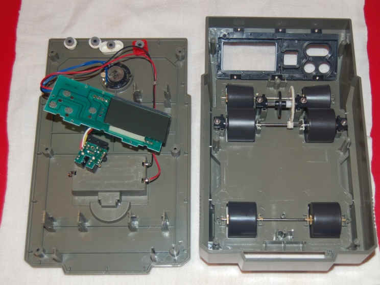
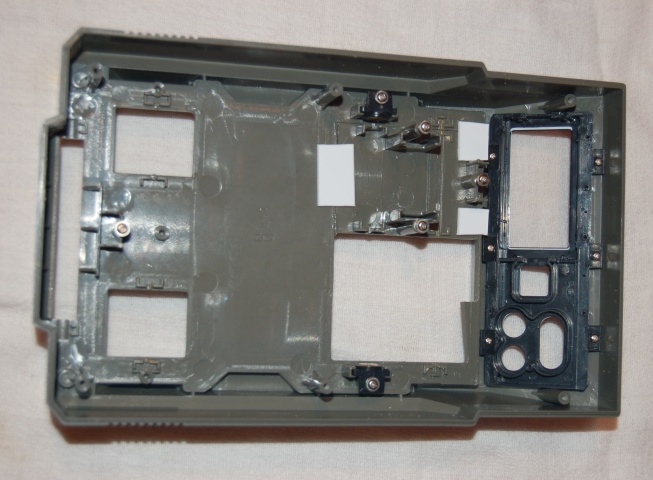
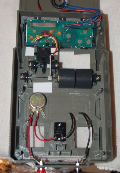
Dyno32 shows the box split open, and the electronic panel removed. This makes it easier to work on the top piece. At this point, check the rollers and axles to make sure they spin true. Swap out parts if they don't. The only parts that are needed to complete the dyno are the middle axle with the gear and rollers. If the axle does not turn true (the middle gear wobbles) it can be swapped out with either of the other two axles. If one or both of the rollers on that axle do not spin true (check against the edge of the opening to look for runout), they can be swapped with one of the other large rollers (although those rollers will need to be glued in place).
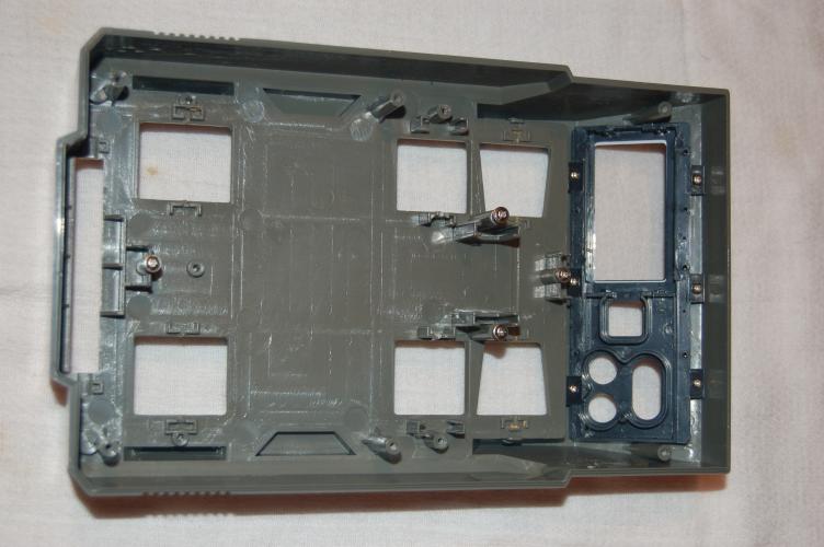
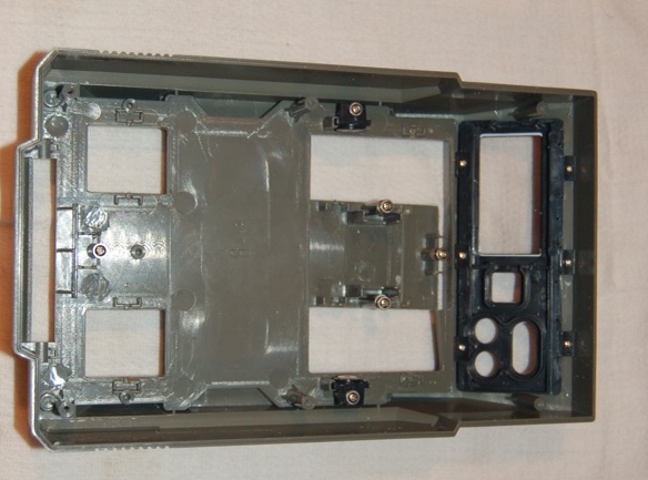
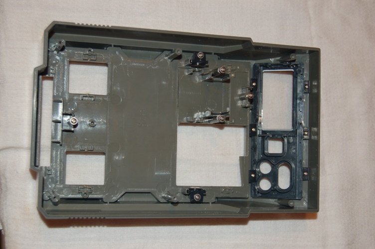
Dyno33 - 35 show the top stripped down, then the cuts made to free the center piece, and finally the center piece moved to its new location. The (Dyno36) shows a mod I did this time around ... I glued some small styrene pieces to the center piece to help it sit flush in its new location, then glued the assembly in place.
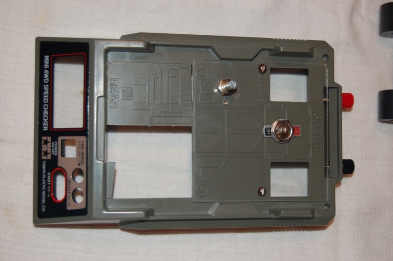
Dyno37 shows the top view. I added a 3 7/8 square piece of 1/8 in plexiglass (Home Depot) to provide a flat surface. I secured it with two bolts (so I can remove it and clean out the junk after drilling the rest of the holes). I drilled holes in the end and installed the power jacks, then drilled holes for the On/Off switch and the pot and installed them. All that's left is to wire everthing together, add some power leads for the car, and reassemble the original hardware.
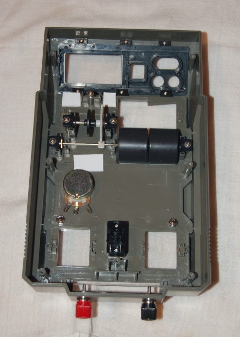
Dyno38 In my opinion, this is the most critical step. After setting up the axle and rollers you have chosen to use, reinstall the assembly as shown. Spin it a few times to ensure there is no rubbing anywhere. I have found that sometimes moving the middle section results in minor rubs. Listen and feel for contact and use an X-acto to trim away plastic where necessary. Re-install the gear assembly and make sure the white gears line up but do not bind. Washers may be needed to move the assembly a little higher so the gears don't bind. Once everything spins freely, you are ready to continue.
I tested all the rollers that came with the box, not just the two that were on the axle. The ones that spin freely were sometimes better and can be glued to the axle and used. I also checked all the axles... some were more true than others.
I tested all the rollers that came with the box, not just the two that were on the axle. The ones that spin freely were sometimes better and can be glued to the axle and used. I also checked all the axles... some were more true than others.
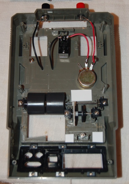
Dyno39 Run wires as shown. I use stranded wire as it bends easier. And I just realized I missed photographing one step. You'll need to drill holes for the guide pin and power braids. Look at Dyno42 as a reference. Set a chassis (without guidepin) on the rollers so the wheels are in the center half of the roller. Insert a small drill bit through the back hole where the guidepin would normally be and drill the hole. Then mount a guidepin on the car and place the car on the box with the guidepin in the hole. Make sure everything lines up right, mark a spot just in front of the shoes for the power taps, and drill your holes. I had been using 1/32 slot car braids for the power taps, but that's a timeconsuming proces so on this box I tried just using wire. The power comes through fine, but the wire does not lie as flat as the braid, and I will probably rework this one.
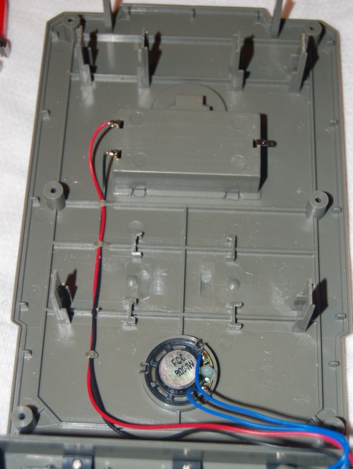
Dyno40 Cut off the posts on the bottom section as shown. Also cut off the two shown at the very top of the photo as they may interfere with the power jacks. (I'm not certain any of them are really needed, but they may help if you accidently step on it) Look closely and you will see a small area above the speaker and slightly left of it that I grooved with a dremel ball bit. The box comes with a groove above and to the right of the speaker for gear clearance. When you move the big white gear, there MAY be contact with the bottom of the box once you reassemble it. I never noticed it before, but on this box it did rub.
Dyno41 Almost done! Put the electronics plate back in place, making sure the small glass piece stays aligned (you may have noticed it is not attached when you pulled the box apart). Also make sure you get the buttons back in the right holes. Once the plate is installed, secure the optical reader piece in place. Then close up the box, making sure not to pinch the wires.
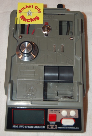
Dyno42 The completed Dyno / Speedchecker. You'll need to add two AA batteries for the electronics to work. I also add a small plexiglas piece just to keep things from falling into the open hole behind the rollers. All you need to do now is hook up a power supply/transformer.
Dyno43 shows one later mod I did was to use pick up braids from 1/32 cars for the power pickups.
The Tamiya box CAN be used to test torque to some degree. You can use the measured distance feature to see how long each car takes to run a scale 1/4 mile. The cars that run quicker are usually developing more torque (or so I tell myself).
The last word on accuracy is always how the car performs on the track.
Updates Sept 27, 2012:
David Parker wrote:
Just making sure credit is given where credit is due... Paul Giganti came up with the original concept of modifying the Tamiya box.
Dave
Paul Giganti wrote:
Thanks Dave. I appreciate the credit. I can't tell you how many hours I stared at the guts of the Tamiya Speed Checker before I took saw in hand. Not wanting to sacrifice even one of the devices in my attempt to figure out how to configure it for HO slot cars, I even resorted to using Photoshop to move parts of a photo around to see if things would "fit." I've always liked your write up and photos of the process; something I never did myself. I haven't made any more of these for a couple years as my source of these devices in China dried up about the same time my HO laser tachometer started to sell very well on ebay.
One note about the rollers of this device previously discussed. It's true that I found many to be out of round, which in the beginning mystified me because I figured pressure molded plastic rollers should be very uniform. After a lot of trial and error I discovered that the culprit was the placement of the brass bearings in the ends of the rollers. Turns out they didn't always mate perfectly to the plastic holes in the rollers exactly centered, and this sometimes (too often) made the rollers run out of round.
I ultimately resorted to putting the rollers in my lathe and turning them down until they were "round." I had to do this WITH the bearings installed, because if I took the bearings out before I machined the rollers, when I put them back in, the rollers were again out of round. I also figured out that the only way to do this correctly, was to remove the two inner brass bearings between the two rollers, glue them together into one piece, THEN machine them together. That finally solved all the problems with the rollers.
This is probably more than anyone would ever want to know about making Tamiya rollers run true in an HO Speed Checker, but perhaps it will be good info for anyone trying to make a smooth running HO device out of something that was never intended to be one.
Paul
Dave Parker responded with:
Not having a lathe myself, my solution was to pool all the axles/pins and rollers, and then mix and match until I found sets that were true. I did find that the rollers with bearings were often the ones out of round, so I ended up using several rollers without bearings (the box comes with both styles included).
Still waiting for someone to develop a computer program and interface so the output can be plotted as speed v. time.


